The first article about STM32duino described “How to start with STM32 like Arduino. The second article of tutorial describes how to control GPIO – digital input, output and also PWM output.
All articles about STM32duino:
STM32duino I. – How to start with STM32 like Arduino
STM32duino II. – control GPIO
STM32duino III. – How to use Serial (USART)
STM32duino IV. – Read temperature and humidity from Si7021 (I2C bus)
In general , STM32 contains a lot of GPIOs which you can use for your aplication.
The power voltage is 3.3V, but some pins (GPIOs) are 5V tolerant. So it means, that the voltage of “Logic One” is 3.3V but you can connect device which has 5V “Logic One” and the STM32 will be still working.
Which GPIOs are 5V tolerant you find in datasheet of your microcontroller.
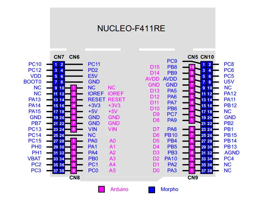
The Nucleo-64 development board contains two types of connectors – Arduino Uno Rev. 3 and Morpho connectors. Arduino connector contains only a few GPIOs, that good for small microcontroller. STM32 microcontroller have a lot of GPIOs so there is Morpho connector where are connected all GPIOs.
The main document which you will need during your working is this.
The document shows labels of Nucleo boards, what jumpers do, “how to program STM32 outside of Nucleo board”.
The main information is also pinout of Arduino and Morpho connectors and schematic of Nucleo board.
As I mentioned above, STM32 contains a lot of GPIOs.
The GPIOs are devidev to PORTs – A port, B, C, D and bigger microcontrollers have more PORTs. Each PORT has (typically) 8 pins (0 up to 7).
The labeling of pins is e.g. PA0 – zero PIN of A PORT, PB5 – fifth PIN of A PORT. And so on.
If you use Arduino library by STMicroelelectronics, the built-in LED is called the same like in other Arduino library – LED_BUILTIN.
The LED is connected to PA5 PIN. How to install STM32duino library you find here.
The each kind of example with STM32duino contains two types of example codes – using of LED_BUILTIN and using of external LED/Button.
If you want to use different GPIO, check this document about STM32 Nucleo development boards.
LED blinking:
Connect the LED (with resistor) between GPIO PC10 and GND. The example code with description is here.
Own LED on different PIN.
// the setup function runs once when you press reset or power the board
void setup()
{
// initialize digital pin PC10 as an output.
pinMode(PC10, OUTPUT);
}
// the loop function runs over and over again forever
void loop()
{
digitalWrite(PC10, HIGH); // turn the LED on (HIGH is the voltage level)
delay(1000); // wait 1000ms
digitalWrite(PC10, LOW); // turn the LED off by making the voltage LOW
delay(1000); // wait 1000ms
}
Using of built-in LED
// the setup function runs once when you press reset or power the board
void setup()
{
// initialize digital pin PC10 as an output.
pinMode(PA5, OUTPUT);
}
// the loop function runs over and over again forever
void loop()
{
digitalWrite(PA5, HIGH); // turn the LED on (HIGH is the voltage level)
delay(1000); // wait 1000ms
digitalWrite(PA5, LOW); // turn the LED off by making the voltage LOW
delay(1000); // wait 1000ms
}
The LED and Buttton:
Again, connect the LED between PC10 and GND. Connect the button between PC11 and GND (PC11 is next of PC10).
If you press the button, the LED is blinking slower.
You can use user button (blue cover) on Nucleo. The User button is connected to PC13.
The LED_BUILTIN is connected to PA5 (or you can use the LED_BUILTIN name). Whole example you find here.
Own LED and Button.
// the setup function runs once when you press reset or power the board
void setup()
{
// initialize digital pin PC10 as an output.
pinMode(PC10, OUTPUT);
// initialize digital pin PC11 as an input.
pinMode(PC11, INPUT);
}
// the loop function runs over and over again forever
void loop()
{
if(digitalRead(PC11)) // read button
{
digitalWrite(PC10, HIGH); // turn the LED on (HIGH is the voltage level)
delay(100); // wait 100ms
digitalWrite(PC10, LOW); // turn the LED off by making the voltage LOW
delay(100); // wait 100ms
}
else
{
digitalWrite(PC10, HIGH); // turn the LED on (HIGH is the voltage level)
delay(500); // wait 500ms
digitalWrite(PC10, LOW); // turn the LED off by making the voltage LOW
delay(500); // wait 500ms
}
}
Using of built-in LED and user button (blue cover).
// the setup function runs once when you press reset or power the board
void setup()
{
// initialize digital pin PC10 as an output.
pinMode(PA5, OUTPUT);
// initialize digital pin PC11 as an input.
pinMode(PC13, INPUT);
}
// the loop function runs over and over again forever
void loop()
{
if(digitalRead(PC13)) // read button
{
digitalWrite(PA5, HIGH); // turn the LED on (HIGH is the voltage level)
delay(100); // wait 100ms
digitalWrite(PA5, LOW); // turn the LED off by making the voltage LOW
delay(100); // wait 100ms
}
else
{
digitalWrite(PA5, HIGH); // turn the LED on (HIGH is the voltage level)
delay(500); // wait 500ms
digitalWrite(PA5, LOW); // turn the LED off by making the voltage LOW
delay(500); // wait 500ms
}
}
PWM output.
Connect the LED between PA0 and GND and the code will be change the light intensity of LED. The exampel code in here.
Own LED – not built-in LED.
// the setup function runs once when you press reset or power the board
void setup()
{
// initialize digital pin PA0 as an output.
pinMode(PA0, OUTPUT);
}
// the loop function runs over and over again forever
void loop()
{
analogWrite(PA0, 250); // PWM output for PA0, shines more
delay(500); // delay 500ms
analogWrite(PA0, 50); // PWM output for PA0, shines less
delay(500); // delay 500ms
}
Using of built-in LED. You can change the PA5 for LED_BUILTIN.
// the setup function runs once when you press reset or power the board
void setup()
{
// initialize digital pin PA0 as an output.
pinMode(PA5, OUTPUT);
}
// the loop function runs over and over again forever
void loop()
{
analogWrite(PA5, 250); // PWM output for PA0, shines more
delay(500); // delay 500ms
analogWrite(PA5, 50); // PWM output for PA0, shines less
delay(500); // delay 500ms
}
And this is end of this article. If you like this article, please, share it and use strong>#STM32duino hastag.

