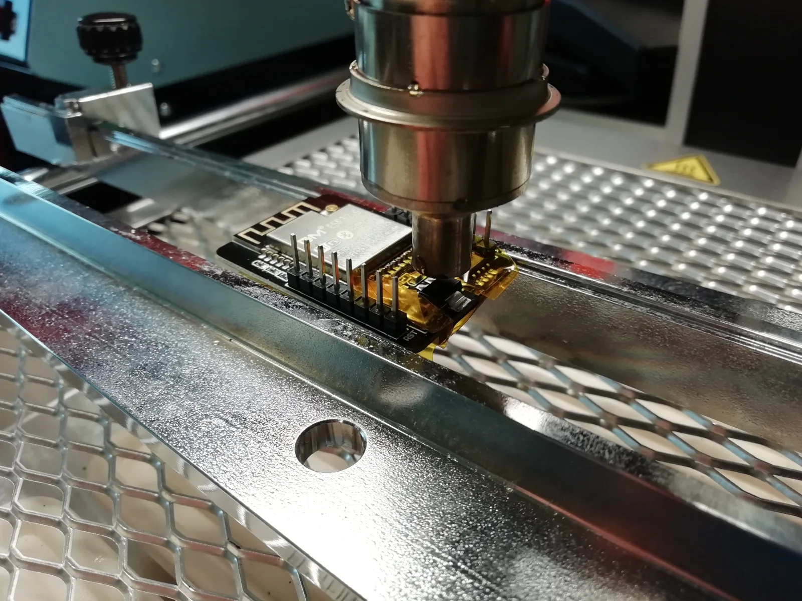
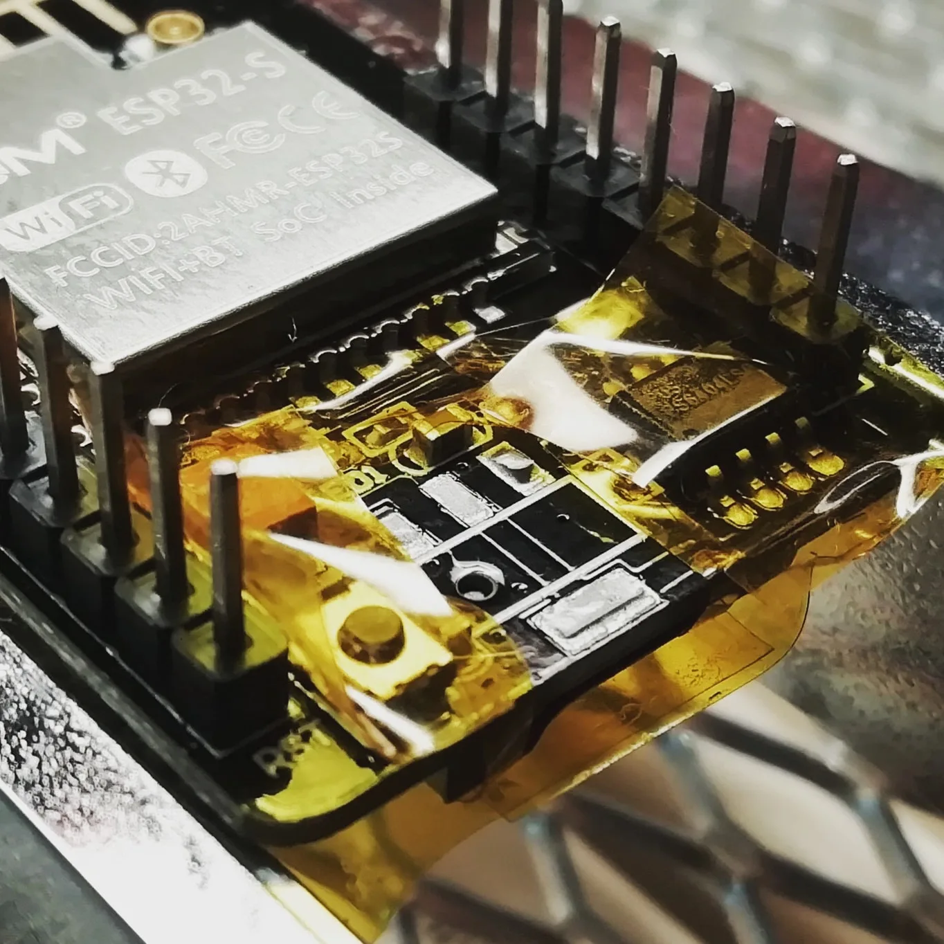
ESP32-CAM is very popular development board which contains Wi-Fi and Bluetooth connectivity with ESP32 module, OV2640 camera, slot for microSD card and programmer – USB-UART convertor.
These parts are designed on 27×40 mm board.
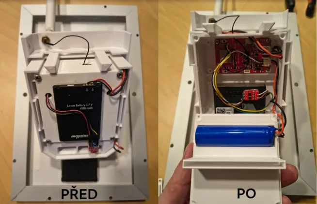
I wanted to power the board by batteries, so my goal was to decrease the current in the deep-sleep mode and also in the runnning mode.
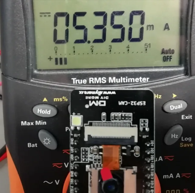
The deep-sleep current was more than 5mA with the default hardware.
My project is focused on easy usage – based on PIR sensor, the ESP32-CAM is wake-up and takes the picture, sends to FTP or by e-mail.
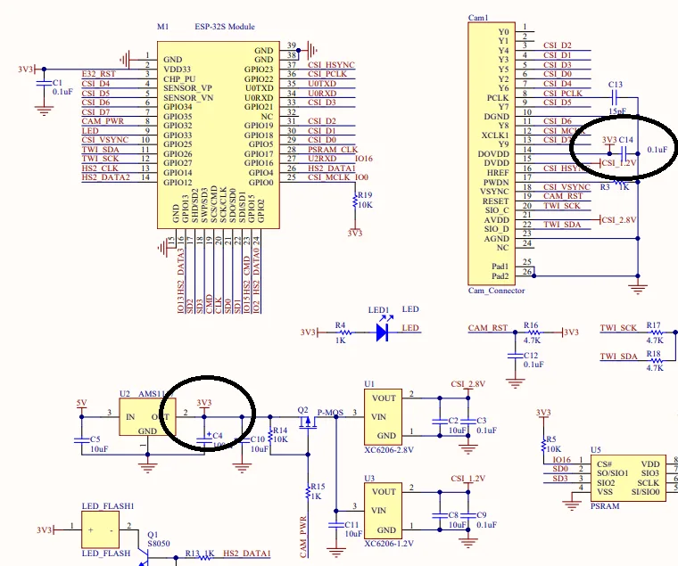
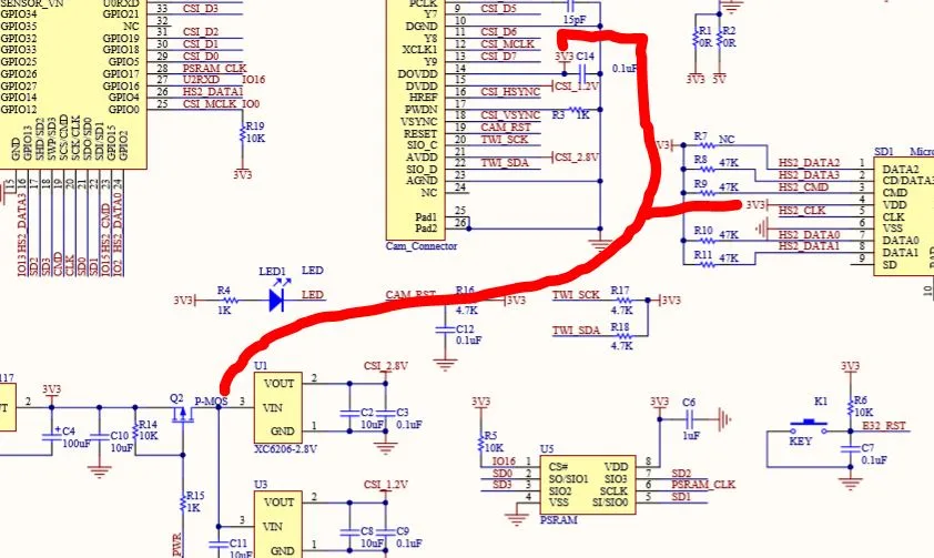
Schematic of ESP32-CAM is here.
On the first look on the schematic, you see where you can save a few miliampers.
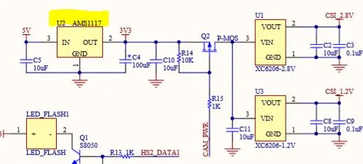
As the default LDO is used AMS1117, it has a few advantages, but also disadvantages – mainly on focus of deep-sleep current.
The quiscent current of AMS1117 is (typical) 5mA, 10mA at maximum. It is too much for device which is powered by batteries.
I replaced the AMS1117 by AP7361C in SOT223R package – R means the same pinout as AMS1117). Based on this easy change, you decrease the the quiscent current of LDO a lot.
If the AMS1117 consumes cca 5mA, the quiscent current of AP7361C is only 60uA.
But I was surprissed when I find out that the deep-sleep current of ESP32-CAM is still more than 3mA. How come?
It is easy, the detasheet specifies the quiscent current as typical value and it means nothing. The quiscent current “should be” around 5mA, 10mA at maximum.
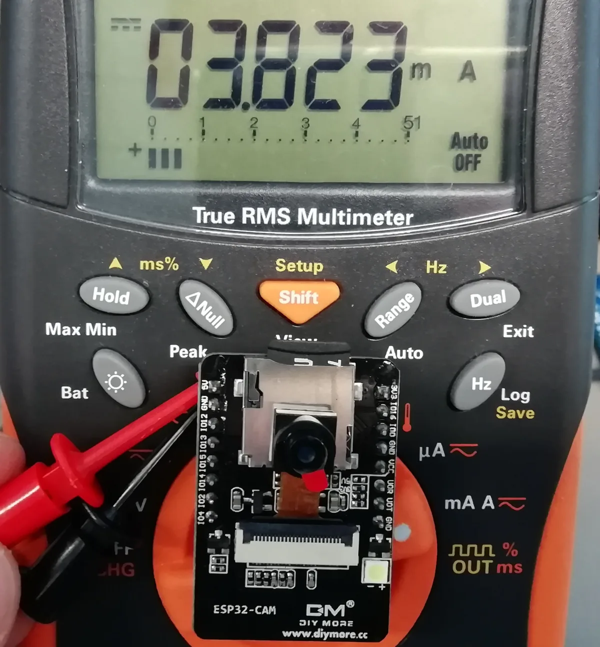
So, the AMS1117 consumes cca 1.5mA.
Ok, so let’s continue…
If the AMS1117 is not the main reason of the high deep-sleep current, what else can cause that?
On the ESP32-CAM board, there are two more regulators for CSI camera – 1.2V a 2.8V.
Nevertheless, there are connected by P-MOSFET transistor, hence theit quiscent current is zero.
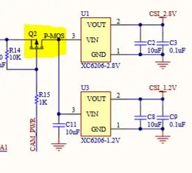
It is good solution of the reducing of current, but, BUT, WHAT IS IT?!
Other power supply of CSI camera is directly connected to 3.3V LDO – AMS1117, AP7361C after replacing.
Maybe this causes the high current.
Ok, I removed the CS camera and set the depp-sleep, the current dropped to 552 uA.
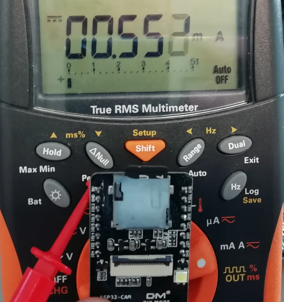
If you remove the microSD card, the current dropped by 200uA… 336uA in total. What is less than 10% of original current.
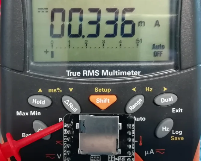
Ok, but what next? If you want to achieve 330uA in the deep-sleep, you have to remove CSI camera and microSD card, but it is import for the project 😀
That’s a pitty, this issue, or bug, should be solved by designers – they just should connect the 3.3V power supply of CSI camera and microSD card on the output of P-MOSFET transistor which is switching two LDOs.
If you don’t want to modify the hardware, you should know the CSI camera OV2640 is supporting deep-sleep modes – software and hardware modes.
software sleep is typical 1mA, 2mA at maximum. If you are able to control the PWDN pin, you can achieve the typical current 600uA, 1.2mA at maximum.
But, there is a problem with controling of PWDN pin in this design – the PIN is grounded through resistor.
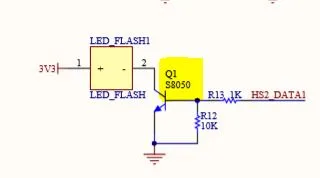
The next issue is the LED which is used for lighting. It is switched by NPN transistor (why???) and the heaet disipation of LED should be much better, because you can destroy the LED by long time working.
Of course, in this project, you can control the ESP32-CAM by switching of PIR sensor.

