Welcome to third part of STM32duino tutorial. What do you expect? We check the most popular microcontroller interface – USART, called Serial in Arduino IDE.
The STM32 microcontrollers includes a few USART buses. The feature of STM32 is possibility to change of USART connection.
All articles about STM32duino:
STM32duino I. – How to start with STM32 like Arduino
STM32duino II. – control GPIO
STM32duino III. – How to use Serial (USART)
STM32duino IV. – Read temperature and humidity from Si7021 (I2C bus)
The USART bus is belongs to most popular microcontroller interface on the world. The bus is so easy.
As I mentioned above, the STM32 microcontrollers includes more USART (Serial) buses. You can use all USART if there will not be a collision with USART connections.
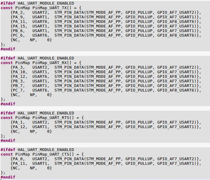
Big feaure is alternative connection of bus. You can easily change the pinout of USART to different GPIO instead of default pinout. There can be more alternative connection.
This document is important for our development. .
Serials and USARTs
The interfaces are called Serial1, Serial2, …
The names of buses you find on “HardwareSerial.cpp“.
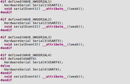
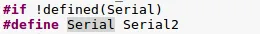
The default name of Serial is USART2 if you will not define differently.
Check the “uart.h” file
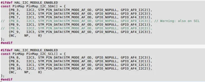
The alternative connection of buses you find on “PeripheralPins.c“.
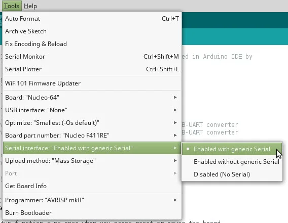
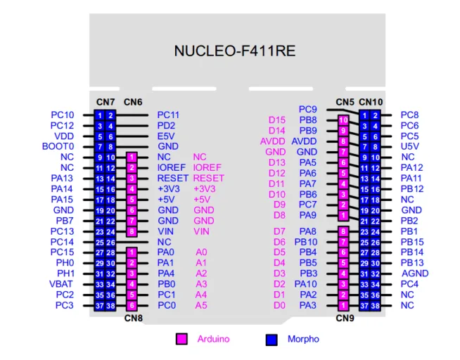
This is printscreen of my Nucleo-64 board.
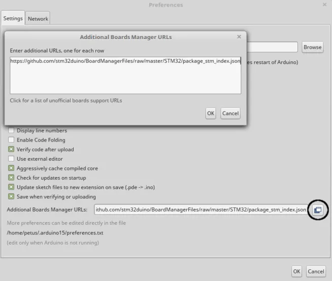
After the installation of Arduino IDE with STM32duino support, you will see a new item, Serial Interface, in Arduino IDE.
Default Serial
The default USART bus, Serial, is ordinarily used for programming of microcontroller and also for communication with laptop through Serial monitor (or other).
STM32 Nucleo-64 are programmed by STLINK/V2-1 programmer/debugger which is includes in Nucleo-64 board.
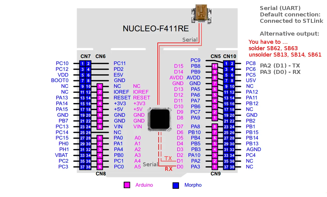
The default setting of Nucleo-64 is this: output of Serial is directly connected to STLINK programmer. The STLINK is also used like USB-UART converter.
The output of Serial bus is not directly connected to GPIO (D1/TX and D0/RX), but it is connected to STLINK programmer. This connection (between STM32 and STLINK) is also conneted to CN3 connector which is available on programmator board.
If you want to connect Serial to D1/TX and D0/RX, you have to change of solder bridges. Solder SMD solder bridges SB62 and SB63 on bottom side of board.
It will be physicaly connected to D0 a D1.
You should disconnet the connection to STLINK – unsolder SB13 and SB14 SMD solder bridges. To avoid collision.
Using of Serial is below.
// the setup function runs once when you press reset or power the board
void setup()
{
// initialize serial:
Serial.begin(9600);
}
// the loop function runs over and over again forever
void loop()
{
// send “Hello World” message through onboard USB-UART converter (STLink)
Serial.println(“Hello World”);
// wait one second
delay(1000);
}
The whole code is available here.
Serial1
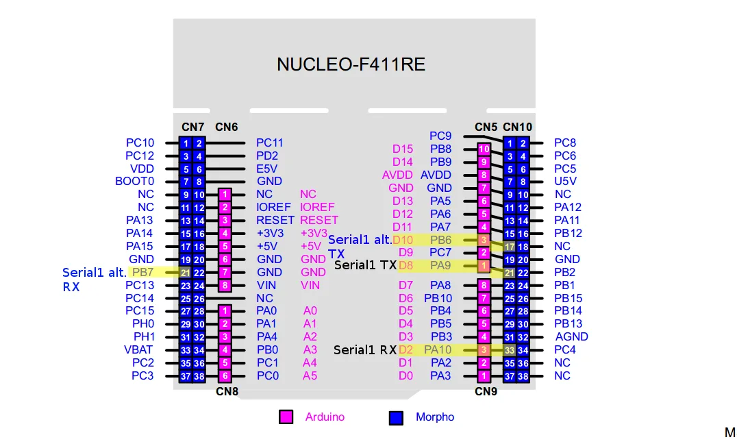
The default pinout of Serial1 is TX – PA9 ( Arduino D8) and RX – PA10 (Arduino D2).
The example of using of Serial1.
// set RX and TX pins
HardwareSerial Serial1(PA10, PA9);
// the setup function runs once when you press reset or power the board
void setup()
{
// initialize Serial1:
Serial1.begin(9600);
}
// the loop function runs over and over again forever
void loop()
{
// send “Hello World” message through Serial1
Serial1.println(“Hello World”);
// wait one second
delay(1000);
}
The important line of the code is HardwareSerial Serial1(rx, tx); which declare Rx and Tx pins.
The whole code is available here.
The example with alternative pinout of Serial1 (TX – PB6, RX – PB7, both on Morpho connector).
// set RX and TX pins
HardwareSerial Serial1(PB7, PB6);
// the setup function runs once when you press reset or power the board
void setup()
{
Serial1.begin(9600); // initialize Serial1
}
// the loop function runs over and over again forever
void loop()
{
// send “Hello World” message through alternative pins of Serial1
Serial1.println(“Hello World”);
// wait one second
delay(1000);
}
The important line of the code is HardwareSerial Serial1(rx, tx); which declare Rx and Tx pins.
The whole code is available here.
Serial6
If you have microcontroller which contains more USARTs, you can use it. For example: Serial6.
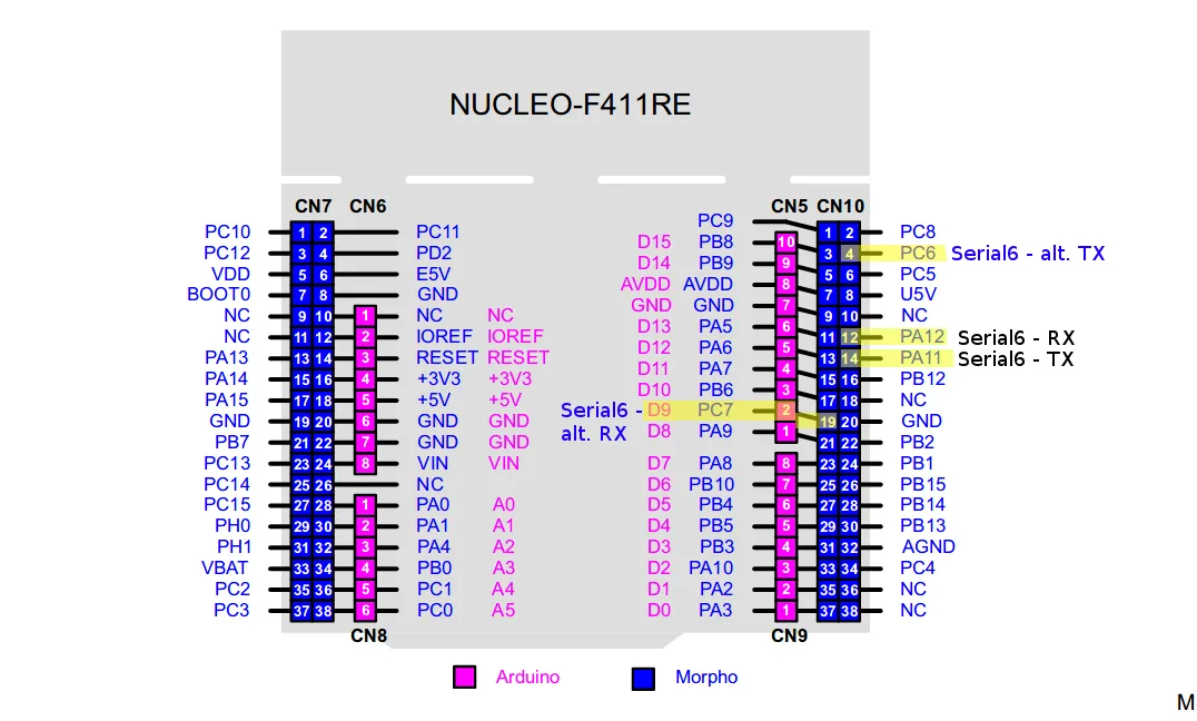
Example with using of default pinout of Serial6.
// set RX and TX pins
HardwareSerial Serial6(PA12, PA11);
// the setup function runs once when you press reset or power the board
void setup()
{
Serial6.begin(9600); // initialize Serial6
}
// the loop function runs over and over again forever
void loop()
{
// send “Hello World” message through of Serial6
Serial6.println(“Hello World”);
// wait one second
delay(1000);
}
The important line of the code is HardwareSerial Serial6(rx, tx); which declare Rx and Tx pins.
The whole code is available here.
The example of using of alternative pinout of Serial6 (TX – PC6, RX – PC7).
// set RX and TX pins
HardwareSerial Serial6(PC7, PC6);
// the setup function runs once when you press reset or power the board
void setup()
{
Serial6.begin(9600); // initialize Serial6
}
// the loop function runs over and over again forever
void loop()
{
// send “Hello World” message through alternative pins of Serial6
Serial6.println(“Hello World”);
// wait one second
delay(1000);
}
The important line of the code is HardwareSerial Serial6(rx, tx); which declare Rx and Tx pins.
The whole code is available here.
And that’s all. If you like this tutorial how to use STM32duino, share it with #STM32duino hashtag.
