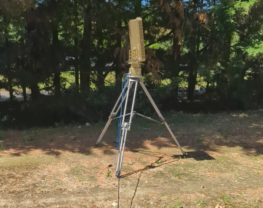
When radar is mentioned, most people picture a metal dish on an airport roof or a giant military installation surrounded by barbed wire. However, the physical principle is no more complex than sonar in a car’s parking sensors – I send out an electromagnetic pulse, wait for the reflected echo, and calculate the distance from the time of flight. What’s out of reach for the average hobbyist is real-time signal processing, precise frequency synthesis, and phase control of dozens of antenna elements.
The project was highlighted by Czech maker Martin Wolker.
The project AERIS-10 (short for Array Electronic Radar with Integrated System) sets out to build a homebrew radar – and everything is made available for free. Schematics, layout (PCB), firmware for FPGA and microcontroller, simulations, BOM. Everything is on GitHub.
Why 10.5 GHz? This band (X-band) has historically been popular for weather radars and highway speed detectors – components for this frequency are relatively accessible, and we have ready-made antennas and reference designs. The wavelength (~2.9 cm) also allows for reasonably small antenna arrays with good spatial resolution.
Note: Operating a radar in the X-band requires regulatory approval (in the Czech Republic from the ČTÚ; equivalent regulators apply elsewhere – FCC in the US, Ofcom in the UK).
Two Versions of the Radar
The project exists in two variants, differing in power, complexity, and intended use. Both share a basic architecture but differ in the antenna system and power stages.
| Parameter | AERIS-10N (Nexus) | AERIS-10X (Extended) |
|---|---|---|
| Frequency | 10.5 GHz | 10.5 GHz |
| Max Range | 3 km | 20 km |
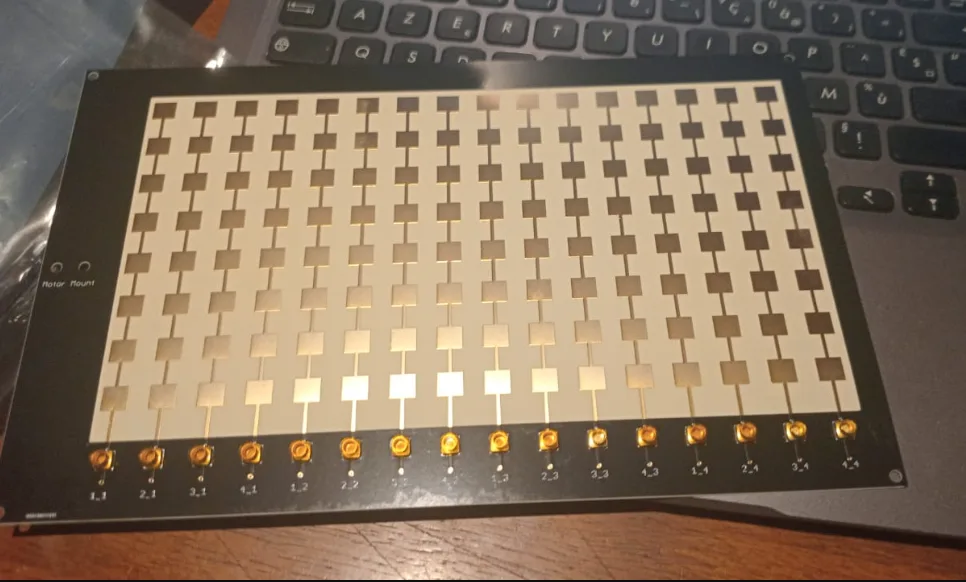
| Antenna | 8×16 Patch Array | 32×16 Slotted Waveguide |
| Beam Steering | Electronic (±45°) | Electronic (±45°) |
| Mechanical Scan | 360° (stepper motor) | 360° (stepper motor) |
| Output Power | ~1W×16 | 10W×16 (GaN amplifier) |
| Processing | FPGA + STM32 | FPGA + STM32 |
The Nexus version targets researchers and experienced hobbyists who want to experiment with radar beamforming and signal processing without building high-power GaN amplifiers. The Extended version adds sixteen separate PA boards with the QPA2962 chip – each capable of up to 10 W in the X-band, resulting in an EIRP that makes the AERIS-10X a serious measuring instrument.
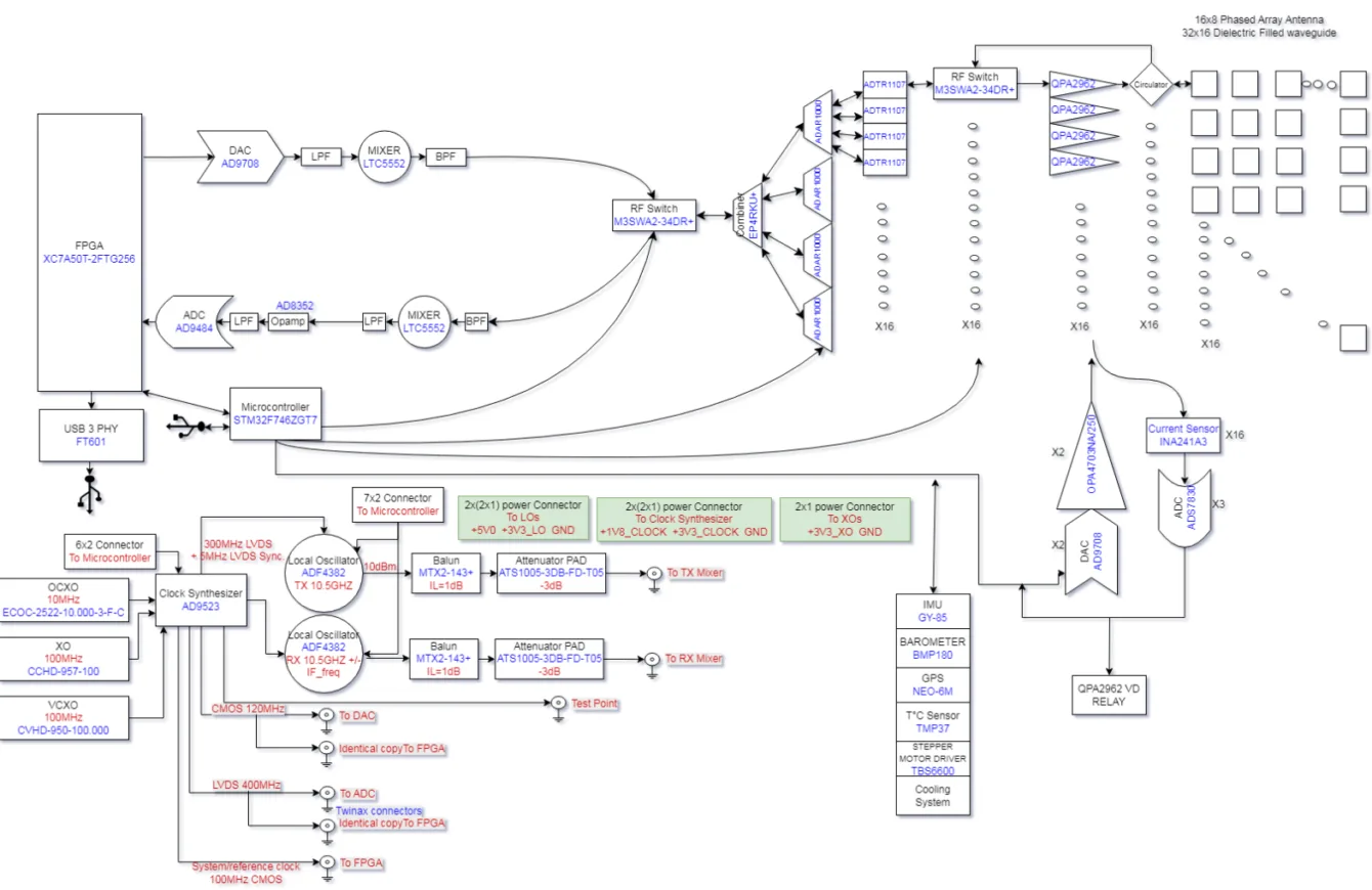
Architecture: What’s Inside
The hardware is split into three modules forming the main backbone of the device.
1. Power Management Board
The radar is very power-hungry – different parts of the circuit require different voltages and, importantly, the correct startup sequence. The power board handles filtering, sequencing, and monitoring. Startup logic is handled by the STM32F746 microcontroller.
2. Frequency Synthesizer
The heart of the entire system in terms of frequencies is the clock signal generator AD9523-1 from Analog Devices. This circuit distributes phase-coherent references to the DAC, ADC, FPGA, and RX+TX frequency synthesizers (ADF4382), which generate the local oscillator for the mixers. Phase coherence is absolutely critical for radar signals – without it, Doppler processing would not work.
3. Main Board (RF + Digital)
This is where all the interesting stuff happens. The DAC generates LFM chirps (more on that shortly), the LT5552 mixers convert the signal to and from the microwave band, and four four-channel phase shifters ADAR1000 control the phase of sixteen antenna elements – all controlled by the Xilinx XC7A100T FPGA (Artix-7) and STM32 microcontroller.
PLFM: Radar Tricks
The abbreviation PLFM in the project name stands for Pulse Linear Frequency Modulated – a pulse radar with linear frequency modulation. What exactly does that mean?
A classic pulse radar sends out a short rectangular pulse and waits for the reflected signal – the echo. A shorter pulse = better distance resolution, but at the same time less energy in the beam = shorter range. LFM elegantly solves this dilemma: a relatively long pulse is sent out, but its frequency changes linearly over its duration (typically increasing) – hence the term chirp – after the short, high-pitched bird call. Upon reception, the echo is processed using pulse compression in a correlator, which compresses the long pulse into a narrow spike with excellent SNR. The result: good range and good resolution simultaneously.
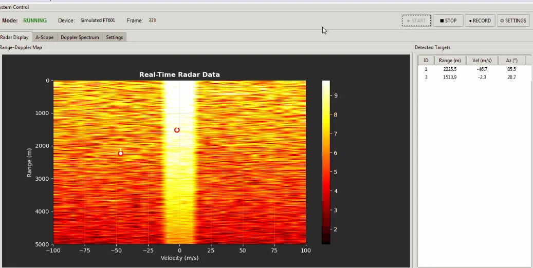
The FPGA in AERIS-10 implements the entire processing chain in Verilog – from raw ADC data through I/Q conversion, decimation and filtering (CIC + FIR) to FFT, pulse compression, Doppler processing, MTI filter, and CFAR detector.
Phased Array: Steering the Beam without Moving Parts
The key technology of AERIS-10 uses electronic beam steering – phased array beamforming. Instead of physically rotating the antenna (which it can also do, using a stepper motor for 360°), the phase at each array element is shifted. The principle is the same as waves on the surface of water: if multiple wave sources emit at different delays, the resulting wave can be directed in any direction.
Beam direction: +19.5°
The ADAR1000 chip from Analog Devices is a four-channel phase shifter with 6-bit resolution – each of the 64 steps corresponds to a rotation of 5.625°. AERIS-10 uses four of them for sixteen antenna elements (TX and RX separately). The result is electronic steering over a range of ±45° in both azimuth and elevation without a single moving part.
Summary
AERIS-10 is a remarkable project for three reasons.
First, technical depth: from the RF frontend through FPGA DSP to Python GUI – no part is hidden behind a black box.
Second, modularity: you can start with one subsystem and gradually add more.
Third, openness: the MIT license means that the results of your work are truly yours.
Building a complete system is not for beginners – it requires experience with soldering BGA and QFN packages, access to RF testing equipment, and solid knowledge of Vivado. But as study material for understanding modern radar systems, AERIS-10 is simply unparalleled.
Project source: PLFM_RADAR on GitHub
The project is very complex and extensive, but also incredibly interesting. This article was processed by Claude AI, and I tried to correct obvious errors. Hopefully, I found them all :)

