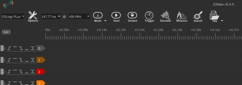
Tomas Jira sent me this article about the hack how to modify DSLogic to DS Logic plus logic anaylzer.
1. Requirements
1.1. Hardware
1.1.1 DSLogic Basic logic analyzer. Could be bought for US$55-60 including shipping
http://www.aliexpress.com/wholesale?ltype=wholesale&isFreeShip=y&SearchText=dslogic&tc=af&isFavorite=n&needQuery=n&isShoppingCard=n&g=y&d=y&isNew=n&origin=y&jump=afs&SortType=price_asc&isBigSale=n&CatId=0&initiative_id=SB_20181125052411&isViewCP=y
1.1.2. MT48LC16M16A2P or compatible 256Mbit SDRAM integrated circuit. It’s dirt cheap and readily available.
http://www.aliexpress.com/wholesale?site=glo<ype=wholesale&g=y&d=y&origin=y&jump=afs&groupsort=1&SearchText=MT48LC16M16A2P&SortType=price_asc&tc=af&initiative_id=SB_20181125053117&isViewCP=y
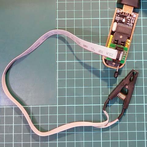
1.1.3. CH314A SPI programmer with SOIC-8 clip. Or any other programmer capable of programming 24C128 EEPROM
1.1.4. Bismuth element to create chip-quik-like desoldering alloy
https://www.ebay.com/sch/i.html?_odkw=bismuth+element&_osacat=0&_from=R40&_trksid=m570.l1313&_nkw=bismuth+mineral&_sacat=0
1.1.5. Others: Apart from the things above you will need a temperature controlled soldering iron, good tacky flux,
Sn60Pb40 solder wire, desoldering braid, tweezers, snip pliers, magnifier glass and some solvant (ispopropylalcohol) to
clean the board after soldering.
1.2. Software
1.2.1. The ASProgrammer software for the CH341A programmer
https://mega.nz/#!Wg43SAxJ!r6kQ59PDk-1VjTKBpALh-W3SiPQPOqMMKI6n3eoNmCg
1.2.2. CH314A windows driver
https://mega.nz/#!X9xlAACC!zzdsre9OwAehpzbSVK-azCGBMxARzgO5cHZCn3B3uW8
1.2.3. The 24C128 EEPROM content file
https://mega.nz/#!j8p3iSZB!-L7zwI02reZQz0ASXzjAxWUnioAEUW1Z70uJY6H2oNQ
2. Preparation
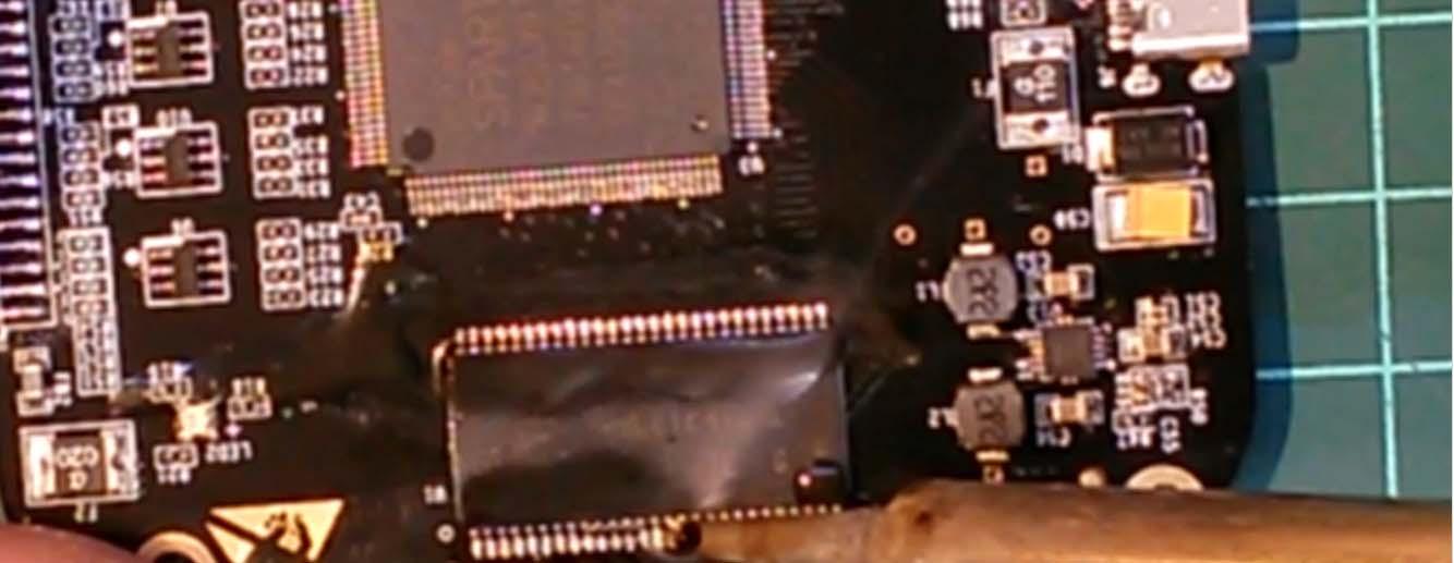
Prepare the PCB for soldering the buffer IC


As you can see, there is a lot of solder on the buffer memory footprint. It has to be removed.

3. Solder the memory buffer IC
3.1. Use good amount of flux and solder braid to wick the excessive solder bumps off. Do not press too much and use
reasonable temperature (about 300°C) in order not to lift some pad and ruin your analyzer.

3.2. Once the pads are flat and nice, carefully place the memory IC on its footprint, check the orientation and alignment
and tack down a pin in the corner with your soldering iron.

3.3. Then do the same with the pin in the opposite corner of the IC.

3.4. Once more check it every pin is aligned to its respective pad and drag solder the remaining pads.
3.5. Apply some new flux and remove solder bridges using solder braid.

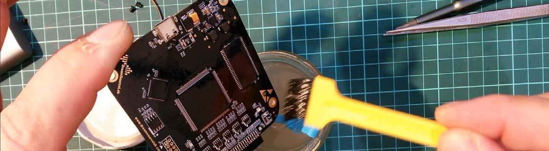
3.6. Rinse your board thoroughly to remove any remaining solder and impurities.

3.7. Repeat the previous step with new solavnt. You really want your high speed bus nice and clean.
4. Prepare your desoldering alloy
4.1. We will use a DIY chip-quik-like alloy to desolder the SOIC-8 EEPROM IC from the board in order to program it.
Although it may seem like it would be possible to program it in circuit, it is not a good idea because you do not want your 5V programmer to poke around the FPGA with its weird voltages and high current draw and the 3.3V Cypress microcontroller. Moreover, it seems that the Write Protect pin of the EEPROM is set active in the circuit. Therefore we will
desolder the IC and program it off-circuit.
The reason behind the desoldering alloy is to lower the melting point of the solder holding the IC in place. That will help
us to remove it without any special equipment while not risking any damage to the IC and the PCB.
4.2. Take your snips and cut off a small piece of the bismuth crystal. Then cut a piece of leaded solder wire sized about
1/3 of the piece of bismuth. The exact ratio is not critical. Put them together on a piece of ceramics or wood. Add good
amount of flux to prevent oxidation.
Set your soldering iron to 350°C as the melting point of pure bismuth his higher than that of solder and melt the bismuth
and solder together. Form a nice bead. The resulting alloy has melting point around 110°C and can be re-used many
times until it saturates with tin or disappears somewhere.
5. Desolder the EEPROM IC
5.1 Put a good amount of flux onto the leads.

5.2. Wet your soldering iron tip well in the alloy and put a good amount of it to the leads of the EEPROM. Let the heat sink
into the junctions on order to let the alloy creep in.

5.3 Do the same on both sides. Then use your tweezers to remove the IC as soon as it is freed from its footprint. Avoid
messing with those 0402 resistors and capacitor nearby.

5.4 Clean the IC thoroughly and connect it to the programmer. Check the orientation. Pin 1 has a small dot nearby on the
IC. Check it again to be sure. Then connect the programmer to your PC.
6. Alter the EEPROM content
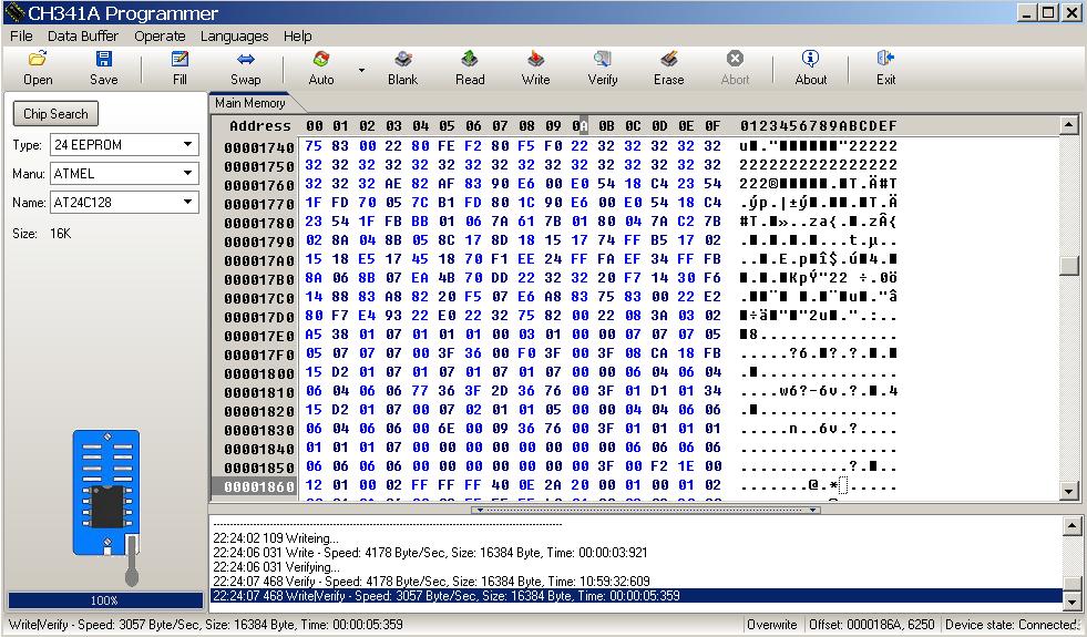
6.1. Install the driver and start the ASProgrammer.
6.2. Read the buffer.
6.3. At the address 00000003 there is the byte of PID that you need to change in order your DSLogic will be detected as Plus instead of Basic. After you read the buffer, there will be number 21 meaning the device is DSLogic Basic. Change that to 20, which mean DSLogic Plus

6.4 Do the same at the address 0000186A.
6.5 Then write the buffer into the EEPROM. Verify.6.6. For your convenience I prepared the original and modified image of the EEPROM content of my device for download, see 1.2.3. I do not know if and how the content changes between devices, if some serial number is stored somewhere or so. Therefore I highly recommend modifying your own EEPROM content against just programming the supplied one into
your device.
7. Clean the pads and carefully re-solder your EEPROM back to the PCB. Check orientation. Avoid messing with those near resistors and capacitor. Clean and inspect the board with magnifier/microscope.
8. And voila – you have a fully fledged DSLogic Plus

