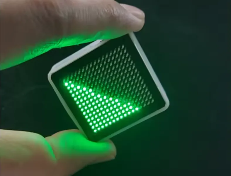
I bought a blinking toy called LED Fluid Simulation on AliExpress – one of those boards full of LEDs that simulates liquid sloshing based on tilt. After taking it apart, something else caught my interest besides what it does. Can it be hacked to dump the firmware and then decode it?
Spoiler right up front: I never got the firmware. I’m sharing the story anyway – maybe it’ll save you a few hours when you run into the same (or similar) hardware.
Inside the toy sits a PY32F403C1 (datasheet) – a dirt-cheap 32-bit ARM Cortex-M4 from Chinese vendor Puyi. These chips cost next to nothing.
Reverse engineering for personal study.
What I had on hand
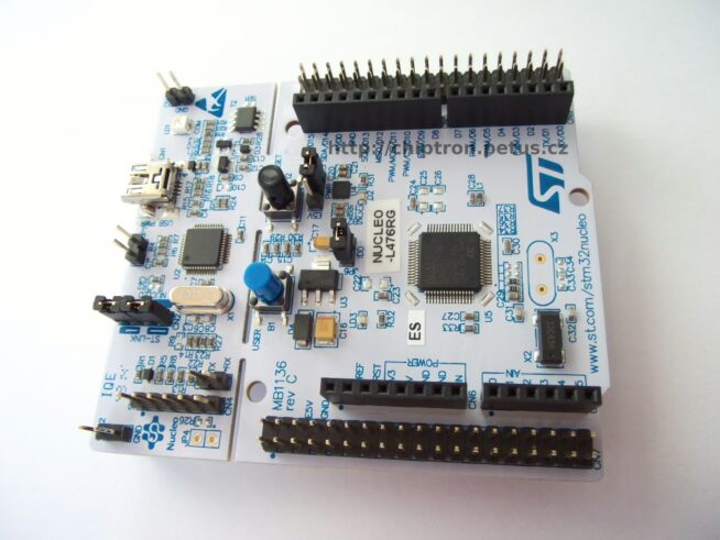
- Nucleo board with built-in ST-Link (NUCLEO-C031C6)
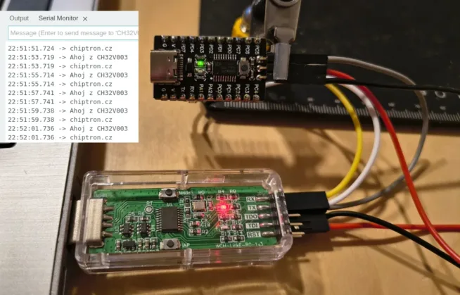
- WCH-LinkE programmer
- multimeter, some wires, a bit of patience
- Windows
The plan was simple: hook up via SWD, dump the flash, done. Maybe even try to decode the binary afterward.
Reality turned out a bit more colorful.
Finding SWD
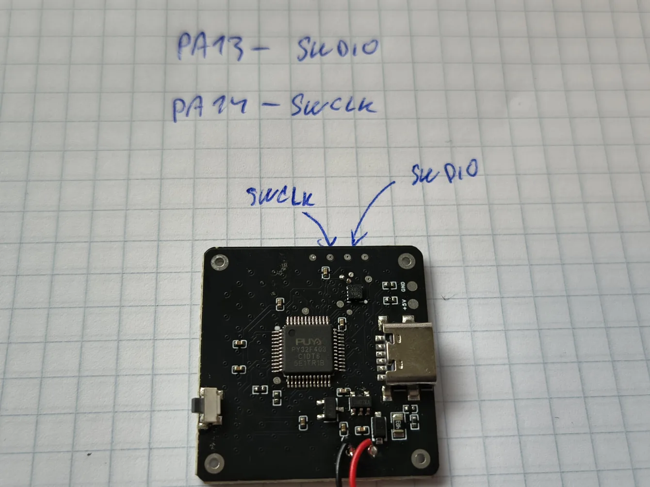
I probed the board and located three pads – SWDIO, SWCLK, and reset. The datasheet told me where they connect, so I just buzzed the test points.
That’s the basics. With SWD you reach an ARM core using two wires plus ground.
First attempt: WCH-LinkE. First roadblock.
WCH-LinkE and the eternal driver fight
The WCH-LinkE is handy and cheap; it handles both ARM and RISC-V. On Windows, though, getting it to work with PyOCD or OpenOCD requires the right driver – and Windows won’t install it on its own. I tried Zadig, forced WinUSB, and the system still refused to see the device.
On Linux it had worked fine (when I was flashing CH32 parts). Probably a PEBKAC issue.
After a while I gave up. I had an ST-Link on the Nucleo anyway, and it enjoys far better support in both PyOCD and OpenOCD.
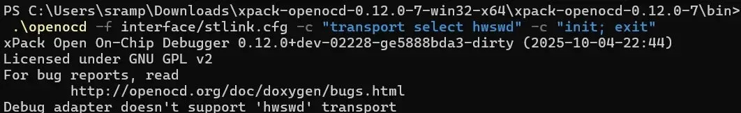
The command
pyocd list --probeskept replying
No available debug probesST-Link from the Nucleo
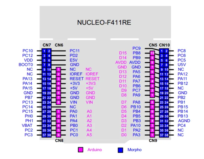
The Nucleo’s built-in ST-Link can drive an external target. Just remove both CN2 jumpers (this disconnects the on-board STM32) and route the SWD signals to the external board.
STM32CubeProgrammer still said “Cannot identify the device”. The detective work began.
The “why won’t it talk” investigation
Standard checklist:
- Power? The board has its own LiPo and 3.3 V regulator; the meter confirmed 3.3 V on the chip.
- Common ground? Connected.
- CN2 jumpers? Removed.
- SWDIO/SWCLK wiring? Checked and correct.
CubeProgrammer’s behavior was briefly confusing. With SWDIO and SWCLK properly connected it reported “Cannot identify the device”. Disconnecting them changed the message to “No STM32 target found”.
It made no sense at midnight, but it does in daylight. Without the data line the ST-Link gets no reply and therefore reports no target. With the lines connected, communication actually works – CubeProgrammer just doesn’t recognize a PY32 by its ID code.
That’s the core problem: CubeProgrammer is built for STM32 parts; the PY32 tells it nothing. Even though the PY32F403 is an STM32 clone 🫣.
CubeProgrammer was out. I switched to OpenOCD, which happily talks to a generic Cortex-M target without insisting it must be an STM32.
OpenOCD and the zero-volt mystery
Another gotcha appeared here.
OpenOCD reported:
Info : Target voltage: 0.000000
Error: target voltage may be too low for reliable debugging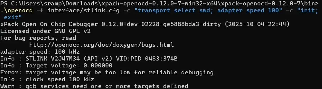
Zero volts? I had already measured 3.3 V on the chip!
The ST-Link measures voltage on its VTREF pin – the target reference voltage that must be tied to the target’s supply. The programmer needs to know what logic level to use for the SWD signals. If VTREF sees nothing, it refuses to talk, even if the chip itself is powered.
Fix: connect VTREF to 3.3 V. Rather than mixing two power rails I simply powered the board from the Nucleo (battery disconnected). Suddenly:
Info : Target voltage: 3.231373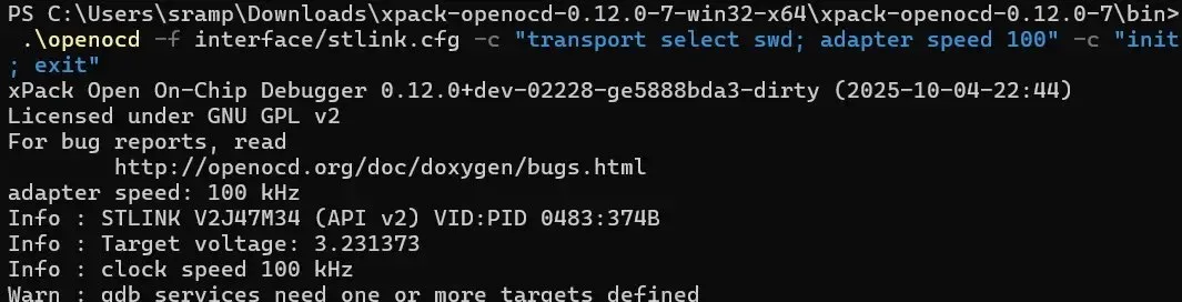
Core captured
After the final tweak:
Info : SWD DPIDR 0x2ba01477
Info : [py32.cpu] Cortex-M4 r0p1 processor detected
Info : [py32.cpu] target has 6 breakpoints, 4 watchpoints
Info : [py32.cpu] Examination succeed
xPSR: 0x61000000 pc: 0x080091d8 msp: 0x20009818
Beautiful. Core detected, halted, program counter in flash, stack pointer in RAM. Everything checks out. The chip is alive and talking; I’m in.
Now just dump the flash:
dump_image firmware.bin 0x08000000 0xC000Then this happened…
RDP protection: dead end
Error: Failed to read memory at 0x08000004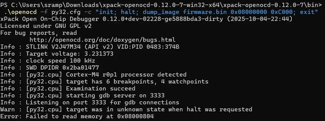
Any attempt to read memory failed. The core can be detected and halted, but the flash yields not a single byte.
Textbook symptom of active RDP (Read-Out Protection). I tried connecting under reset (connect_assert_srst), reset halt, dropping the clock to 15 kHz, reading word by word. The core even halted cleanly at the reset vector. Flash stayed silent.
Clear conclusion: the firmware is behind read protection and I’m not getting it out.
A cheap Chinese toy has its memory locked…
Why you can’t just bypass it
RDP is a hardware barrier. It exists precisely to stop what I was trying to do. Erasing the chip isn’t a workaround either – it would most likely disable JTAG/SWD afterward, leaving you with no way back in.
The question is which RDP level the PY32F403 actually implements.
More advanced techniques exist – decapping, glitching, voltage fault injection – but they require specialized gear, time, and expertise. For a toy that cost a few bucks, none of that makes sense.
Addendum: could RDP still be bypassed?
After publication, community member MarSik (https://witter.cz/@marsik) pointed me to an interesting paper showing that RDP is not completely bulletproof.
Two researchers demonstrated bypassing RDP level 1 on an STM32F4 using voltage glitching – a fault-injection attack.
The idea is simple on paper and brutal in practice: at a precisely timed moment you induce a short voltage dip on the supply that makes the processor skip the instruction checking whether read protection is active. If the timing lands right, the bootloader spits out data it would otherwise refuse.
They used a Teensy as the glitcher, a custom MOSFET injection circuit powered from the VCAP pin, an oscilloscope for tuning, and a lot of patience – the full firmware was extracted after roughly 22 hours and 1024 successful glitches out of more than 600 000 attempts.
Fascinating read, but also a reminder that this is an entirely different league from plugging in an ST-Link: irreversible hardware modification, specialized equipment, and days of tuning.
Note that the work targets the STM32F4 specifically. The PY32F403 is a clone and behaves similarly, but it is not guaranteed to be identical. Power management, VCAP pin locations, and bootloader behavior may differ, so the entire characterization would have to be repeated from scratch for the PY32 – and success is not assured.
For the firmware of a blinking toy it’s still not worth it, but it does prove RDP has limits. Source: https://jerinsunny.github.io/stm32_vglitch/
The entire process was run by an AI agent
And now the part I have to admit. I didn’t solve any of this alone. An AI agent (Claude Opus 4.8 High) drove the strategy – I just supplied the hands and the eyes on the screen. Trained monkey? 😀
It worked as a dialogue. I described what I had and what I wanted. The agent proposed the next step, I wired it up, ran the command, copied the output back. The agent read it, suggested the following move. Repeat. Yes, trained monkey. 🫣
Specifically the agent:
- outlined the whole strategy – from the first WCH-LinkE attempt through the switch to OpenOCD,
- diagnosed error messages and explained what they meant,
- wrote the actual OpenOCD commands and the contents of the
py32.cfgtarget file for a generic Cortex-M, - correctly identified that silent flash with a working core connection meant RDP, not a wiring mistake.
It’s not that the AI “hacked for me.” It kept the structure, remembered context across dozens of attempts, and treated every error message as information rather than a dead end.
The takeaway: with a good AI agent, even someone who isn’t an SWD or OpenOCD expert can dive into hardware reverse engineering (me 😀). The agent knows command syntax, common pitfalls, and the Cortex-M memory map. You bring the hands, patience, and willingness to experiment.
What I took away
I didn’t get the firmware. That’s actually good news about something else: even the cheapest chip in the cheapest toy can ship with read protection enabled. Wait – that’s not good news! 😩
Puya’s RDP works. Plenty of people assume Chinese no-name hardware is wide open – here’s proof it isn’t always. Unfortunately.
Most of the problems I hit had nothing to do with this specific chip and everything to do with generic SWD debugging:
- Don’t marry one programmer. When the WCH-LinkE won’t cooperate, the ST-Link might (and vice versa).
- VTREF must see voltage. The chip can be powered and you’ll still get nowhere until the ST-Link sees a reference voltage. I didn’t know that 😐 (or the AI agent was wrong).
- Watch CubeProgrammer’s messages. “Cannot identify the device” on a PY32 doesn’t necessarily mean bad wiring – it just means the tool doesn’t recognize a non-STM32 by ID. Don’t let it send you down the wrong path.
- OpenOCD is more universal. For foreign Cortex-M parts a generic target is far more flexible than CubeProgrammer.
So yes, a failure. But an instructive one – both about cheap microcontrollers and about using an AI agent.
Product note: Power-on is a single button on the side of the board. The enclosure is 3D-printed.
Power-off works by placing the board LEDs-down and leaving it untouched for about ten seconds – it shuts itself off.
Link to the LED Fluid Simulation
Tools used: OpenOCD (xPack build), ST-Link on NUCLEO-C031C6, Zadig (WinUSB driver), multimeter, and plenty of patience.
PY32 parts you can actually program easily
If the PY32 caught your eye but you want a smoother on-ramp than wrestling with the F403, grab the cheaper PY32F002, PY32F003 or PY32F030 series – the most common parts that the community actually supports.
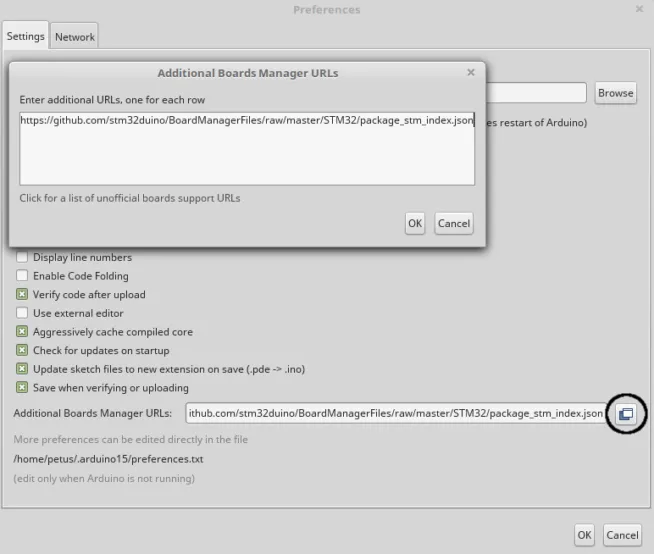
Unlike the F403 (Cortex-M4) these are simpler Cortex-M0+ cores, but they come with ready-to-use infrastructure: the community Arduino core (py32duino/Arduino-PY32) lets you program them straight from the Arduino IDE the way you already know, PlatformIO has board definitions for the F003/F030, and ready-made GCC/CMake templates (IOsetting/py32f0-template, decaday/py32f0-cmake) produce a working binary in minutes.
You can flash them with the same ST-Link you already have running, or with a cheap DAPLink. For learning and first LED blinking this series is far more pleasant – save the F403 for when you feel like hand-rolling a toolchain.


